

Working Principle of a Spectrum Analyzer Explained with Block Diagram
Understanding signals is a fundamental requirement in electronics, communication, and audio engineering. While instruments like oscilloscopes show how a signal changes over time, engineers often need deeper insight into which frequencies are present in a signal and at what strength. This is where a spectrum analyzer becomes essential.
In this blog, we will clearly explain spectrum analyzer, explore the spectrum analyzer working principle, and break down its operation using a block diagram, with special focus on the audio spectrum analyzer for practical understanding.
What Is a Spectrum Analyzer?
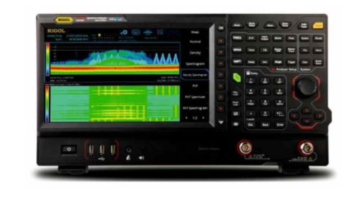
A spectrum analyzer is an electronic test instrument that measures and displays the frequency spectrum of a signal. Instead of showing voltage versus time (as an oscilloscope does), it displays amplitude versus frequency. This allows engineers and students to see how signal power is distributed across different frequencies.
Spectrum analyzers are widely used in:
Audio signal analysis
Wireless communication systems
RF and microwave engineering
EMI/EMC testing
Academic laboratories and research
An audio spectrum analyzer is a specialized form designed to analyze signals in the audible frequency range, typically from 20 Hz to 20 kHz.
Spectrum Analyzer Working Principle: Basic Concept
At its core, the spectrum analyzer working principle is based on converting a signal from the time domain into the frequency domain and measuring its amplitude at each frequency.
The basic idea involves:
Accepting an input signal
Separating or sweeping through its frequency components
Measuring signal strength at each frequency
Displaying the result on a frequency vs amplitude graph
Most traditional spectrum analyzers use the superheterodyne principle, which relies on frequency mixing and filtering to analyze signals accurately.
Detailed Explanation of Spectrum Analyzer Block Diagram
1. Input Attenuator
The input attenuator controls the strength of the incoming signal. Signals entering a spectrum analyzer can vary widely in amplitude.
The attenuator:
Prevents damage to internal circuits
Ensures accurate amplitude measurement
Helps maintain linear operation
For audio spectrum analyzers, this is especially important when dealing with high-level audio outputs from amplifiers.
2. Mixer
The mixer is a key component in the spectrum analyzer working principle. It combines the input signal with a signal from the local oscillator.
The output of the mixer contains:
The sum of input and LO frequencies
The difference of input and LO frequencies
This frequency conversion process makes it easier to analyze a wide range of frequencies using fixed filters.
3. Local Oscillator (LO)
The local oscillator generates a frequency that sweeps across a defined range. As it sweeps, different frequency components of the input signal are converted to the same intermediate frequency (IF).
This sweeping action allows the spectrum analyzer to:
Scan the entire frequency range of interest
Identify individual frequency components
In audio spectrum analyzers, the LO sweep covers the audio frequency band.
4. IF (Intermediate Frequency) Filter
The IF filter selects a narrow band of frequencies from the mixer output. This block determines the resolution bandwidth (RBW) of the analyzer.
Key points:
Narrow RBW -Better frequency resolution
Wider RBW - Faster sweep time
The IF filter plays a critical role in separating closely spaced frequencies and improving measurement accuracy.
https://scientechworld.com/spectrum-analyzer/
64 Visualizações